|

|
|
|
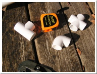
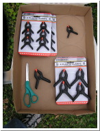
This photo shows some things that you will need. Clockwise from left to right are a T-joint coupling, a tape measure ruler, an X-joint coupling, and a L-joint coupling. I used ¾ inch plastic PVC pipe, so the couplings are for this size piping. All the joints have 90 degree angles, which makes a triangular shape tough to construct. The T-joint and the L-joint couplings are cheap, about 30¢ apiece if bought separately, or less than 20¢ apiece if bought in bags of ten or twelve. The X-joint coupling was more expensive at over a dollar apiece. I guess plumbers dont have much need for such a joint. The most valuable tool is a tape measure ruler. You need to measure everything before making any cuts. |
The pipe cutter is the most important energy saving device you can have in constructing your cold frame. The pipe cutter can do easily in seconds what will take minutes with a lot of effort if you use a hacksaw to cut your pipe. This one I bought for a minor bathroom-plumbing project years ago. It was worth its weight in gold for this project. |
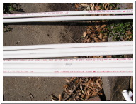
This photo shows _ inch plastic PVC pipe for drinking water. Later I was to realize that I should have bought plastic PVC pipe for non-potable water. I had some of that in my garage and compared the two. . The difference is in the pipe wall thickness. The drinking water version is twice as thick. This makes the drinking water version much stronger but less flexible. This mistake caused my initial plans to be faulty due to this lack of flexibility. The drinking water pipe costs about two dollars for a ten-foot section. |
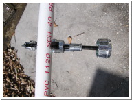
This photo shows how to set up the pipe cutter. You put the roller blade (on the left) on the measured mark (red dot). You use the screw handle (on the right) to tighten the pipe cutter as you roll it around the pipe while cutting. |
|
|
|
|
This photo shows how to set up the pipe cutter from another perspective. You can see that it is an old pipe cutter. It reads that it was made in the U.S.A. |
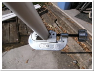
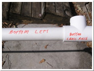
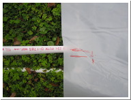
This photo shows how I labeled the pipeline parts. This should help me when I put it back up next year. |
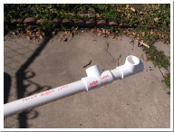
I put the small parts together on bigger pieces, so that when I laid it out before construction, I wouldn't have a bunch of small pieces laying around confusing me. . I did not use glue, because I want ease in both construction and take down. I just fit the pipe into the connectors. You can see here the use of two right angle connectors to make an angle different than 90 degrees. |
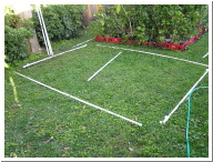
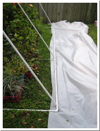
I laid out the pipeline parts before construction. |
|
|
|
|
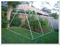
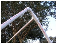
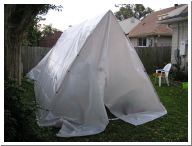
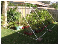
Here is the frame fully constructed. It looks real nice, but the design had a fatal flaw. The triangular shape had a 10-foot base and 9.5-foot upright sides. The calculated angle at the top is 63.5 degrees forced into a 90-degree fitting using rigid drinking water PVC pipe. This puts strain on the uprights. They want to fit in the 90-degree connector, so they start spreading at the other end, causing the sides to spread. I did not realize this at the time. I corrected this problem later. |
Here is a detail view of the upper right side corner. |
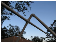
Here is a detail view of the upper center connections. |
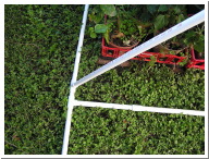
Here is a detail view of the ground level center connections. You will note that the ground cross piece was made of two pieces joined together with a straight-line joint coupling. This was because I miscounted when I counted the number of long pieces of PVC piping that I needed from my hand written plan drawing. I was short one pipe length. I had a leftover piece of ¾ inch PVC pipe in the garage from an air conditioner drain project I had done years ago. It was for non-drinking water and in comparing the two types of piping; I discovered the differences between the two. |
|
|
|
|
Here are some clamps I bought from the dollar store. The clamps in the six-pack fit the pipe, but were not strong enough to withstand windy conditions. The clamps in the four-pack worked fine. |
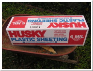
Here is the most expensive part of the project. This is a box of 100 feet by 20 feet of 6-mil clear plastic that cost $80.00. I view it as an investment. Used in 25-foot sections, it will last four years. |
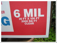
The description reads 6-mil CLEAR plastic. The plastic looks opaque to me, as you will see. |
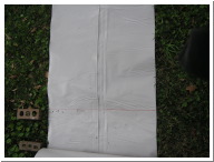
This is what the plastic looks like as you roll is out. |
|
|
|
|
I used bricks to mark my measurements and a red marker pen to draw the cut line. |
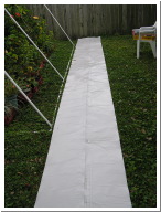
I used a red marker pen to draw alignment marks to properly place the plastic sheeting before covering the frame. I'm embarrassed that this photo also shows the invasive winter weeds in my St. Augustine grass backyard lawn. |
The plan was to tuck six inches of sheeting under the base on each side, using 19 of the 20 feet width of the plastic sheeting to cover the cold frame. |
Here’s the fully covered frame. It doesn’t look like CLEAR plastic to me. The plan is to uncover the ends of the frame during above freezing conditions. For freeze predicted nights, the ends will be closed off and clipped. In the upper left corner, you can see some blooms from my neighbor’s Lipstick garden-variety hibiscus. |
|
|
|
|
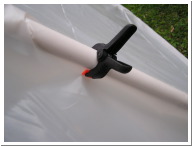
Here's a better look at the clip in use. |
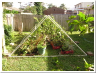
On the first cold night, the winds caused the sides to widen and the center to collapse. I put it back together using more clips and big bricks on the ground connections to prevent ground level spreading. The next cold windy night collapsed the structure again. Both times I was so intent on fixing the problem, I forgot to photograph the collapse. With my daughter’s help, I calculated the upright lengths needed to conform to a 90-degree top connection. My uprights were cut from 9.5 feet to 7.07 feet. The height of the structure was reduced from 8 feet high to 5 feet high. You can see the bricks used to brace the frame. |
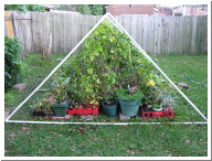
Here's an end view used to check if all the plants will fit under this lower ceiling configuration. They don't. I will need to do some rearranging and some judicious pruning. |
Now they all fit. . The weather is warm, so I’ll leave the plastic off for now. With this lower peak, it will be much easier to put the plastic on and take it off. Putting on plastic sheeting will be much easier than lugging all these potted plants in and out of the garage this winter! |